


Products for which the sale has been cancelled.

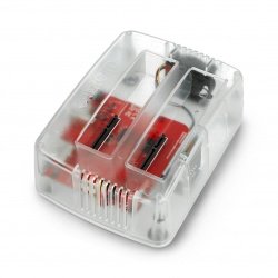
Case for Raspberry Pi Zero x2 - Mini Cluster - open - PiHut TPH-067
Index: PIH-21312
- Reduced price
- Sale

- Reduced price
- Sale
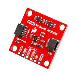
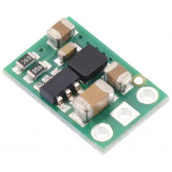
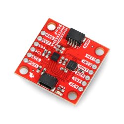
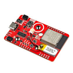
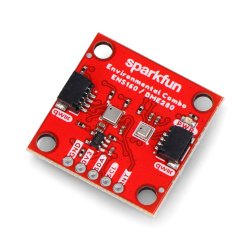
Qwiic 5V Boost - 5V step-up converter - AP3012K - SparkFun PRT-28203
Index: SPF-26595
- Reduced price
- Sale

Withdrawn products


See also