- Sale
- SPECIAL OFFERS
Description
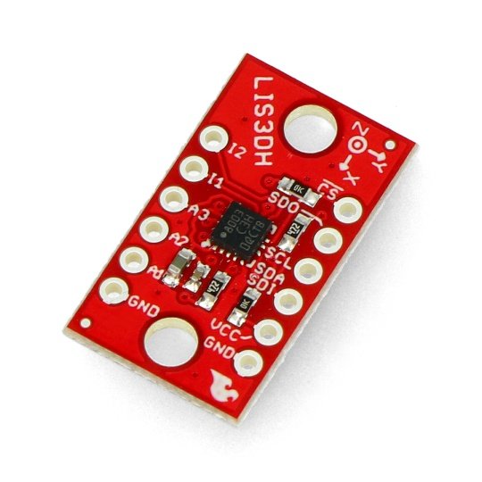
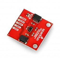
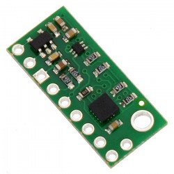
The MEMS module allows you to measure acceleration in three axes in three-dimensional space. The device communicates via the SPI or I2C bus. In addition, it has a built-in temperature sensor, integrated FIFO buffer and programmable interrupts that enable, i.a. the detection of free decrease.
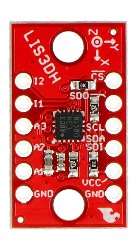
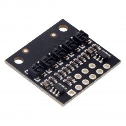
To communicate with the central unit, the user can choose the interface SPI or I2C. The module has necessary for the correct operation of the system, passive elements. The pins are holes for soldering goldpin connectors(not included) to connect the sensor viawires or to directly attach to breadboard.
Specification
- Operating voltage: 1.7 V to 3.6 V
- Communication interface: I2C or SPI
- Accelerometer:
- 3 axis: X, Y, Z
- Adjustable range: ± 2 g, ± 4 g, ± 8 g, ± 16 g
- Resolution: 10 bits
- Pins: holes for goldpin connectors - 2.54 mm pitch
- Built-in temperature sensor and FIFO queue
- Programmable interrupts that enable, i.a. the detection of free decrease
- Jumper that enables disconnection of the resistors pulling up the line of the I2C bus
- Two mounting holes with the diameter: 3mm
Details concerning the technical parameters of the sensors can be found inthe documentation.
The maximum voltage, with which the system works is 3.6. The sensor can be directly connected to the Arduino to communicate via I2C. In case of the SPI bus, needed is a voltage converter. The exceptions are the modules operating with voltages of 3.3 V, for example,Arduino Pro Mini 328 - 3.3 V/8 MHz.
|
The product is compatible with Arduino To facilitate the work with this module, manufacturer prepared auser manualalong with a sample program for the Arduino and design files with a library available inthe GitHub service. |
Pins
The sensor has pins for mounting goldpin connectors - 2.54 mm pitch (not included, purchased separately and self-soldered).
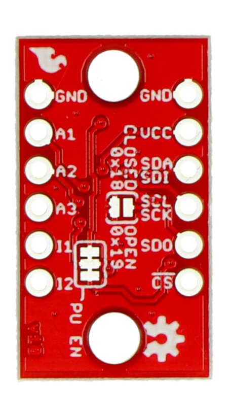
| Pin |
Description |
|---|---|
| VCC |
Supply voltage of the I/O pins of the system from 1.7 to 3.6. |
| GND | The ground of the system. |
|
A1 A2 A3 |
The analog inputs. |
|
I1 I2 |
Outputs of interrupt. |
| CS |
Chip select in SPI communication. |
| SDO |
The output of the MISO data in the SPI communication. |
| SCL | Clock input in the I2C and SPI communication. |
| SDA / SDI | The data line in the I2C communication and MOSI for SPI. |
Useful links |
