


Products for which the sale has been cancelled.
- New
- New
- Sale

- Reduced price
- Sale
- Reduced price
- Sale
- Sale
- Sale


Products: 1
Loading...
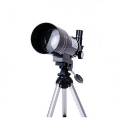
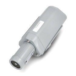
Opticon telescope Apollo 70F300AZ 70mm x150
Astronomical telescope with a large lens that provides high quality images of distant objects. The Apollo 70F300AZ provides a wide viewing range. A dedicated 3x Barlow lens...
Index: GFR-20303
Index: GFR-20303
- Discontinued product
See also